Viewer and Part Status
Look at the assembly and decide reuse, repair, or replace for each part.
Before you start
You need an inspection report with an assembly already uploaded. See New Report and Upload.
How to get there
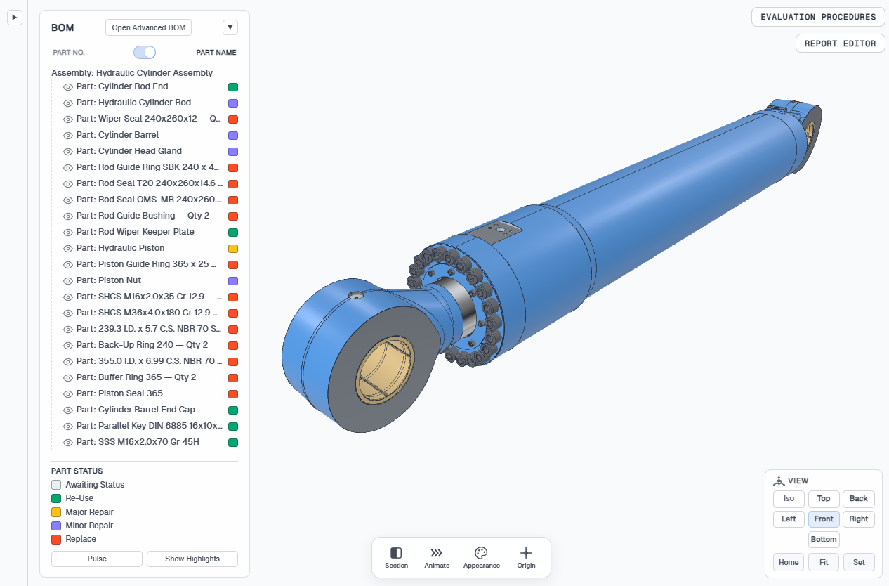
In the workspace, click the inspection card. The Model Viewer opens for that report. From here you can set part status and open Evaluation Procedures or the Report Editor without leaving the viewer.
Viewer controls
Orbit, pan, and zoom in the 3D viewport. The same demos appear in the app from the ? help menu → Viewer Controls. Switch Mouse or Trackpad below. Home, Fit, and Set are also covered in View cube.
Choose Mouse to see the pointer and wheel gestures for moving around the model.
Orbit
Hold the middle mouse button and drag to rotate the model around its center.
Pan
Hold the left mouse button and drag to slide the model left, right, up, or down.
Zoom
Scroll the mouse wheel to move closer or farther from the model.
Home
Centers the model, restores the fit zoom baseline, and snaps to the Front view.
View → HomeFit
Zooms so the whole model fills the viewer while keeping the current orientation.
View → FitView directions
Use Iso, Top, Front, and the other View buttons to snap to standard orientations.
View cubeSet orientation
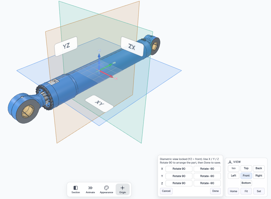
Set opens a single panel with Rotate 90 / −90 on X, Y, and Z. With Origin on, the triad stays locked at the viewer center while you snap the model onto the axes.
View → SetModel tree
The left panel is the BOM for the loaded assembly. Click a row to select that part in the 3D view. Use the eye icon to hide or show a part. Switch the list between Part No. and Part Name with the toggle at the top of the tree.
Click the color square on a row to set part status. Hold Ctrl (or Cmd on Mac) and click to select several parts, or hold Shift to select everything between two lines. The legend under the tree uses the same colors:
- Awaiting Status — no outcome yet
- Re-Use — part can go back into service
- Minor Repair — limited work, then back in service
- Major Repair — substantial work before reuse
- Replace — part should not return to service
Status on the tree feeds the report and Generate. Re-Use, Minor Repair, Major Repair, and Replace become the disposition language on the PDF. Awaiting Status stays in the tree and can still print unless you hide that part block in the Report Editor with Show/Hide. Generate has little to go on until you set a status. Keep the same vocabulary across the BOM before you write the inspection narrative.
Advanced BOM
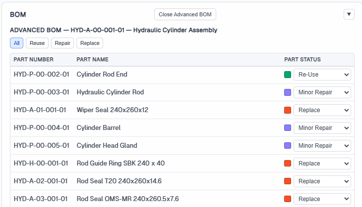
Click Open Advanced BOM in the tree header for a table of every part with status filters: All, Reuse, Repair, and Replace. Use it when you need a spreadsheet-style pass through the assembly instead of the compact tree. If the report has a schematic, Show Schematic places the drawing above the table so you can zoom and pan while you work the rows.
Pulse and Highlight Sync
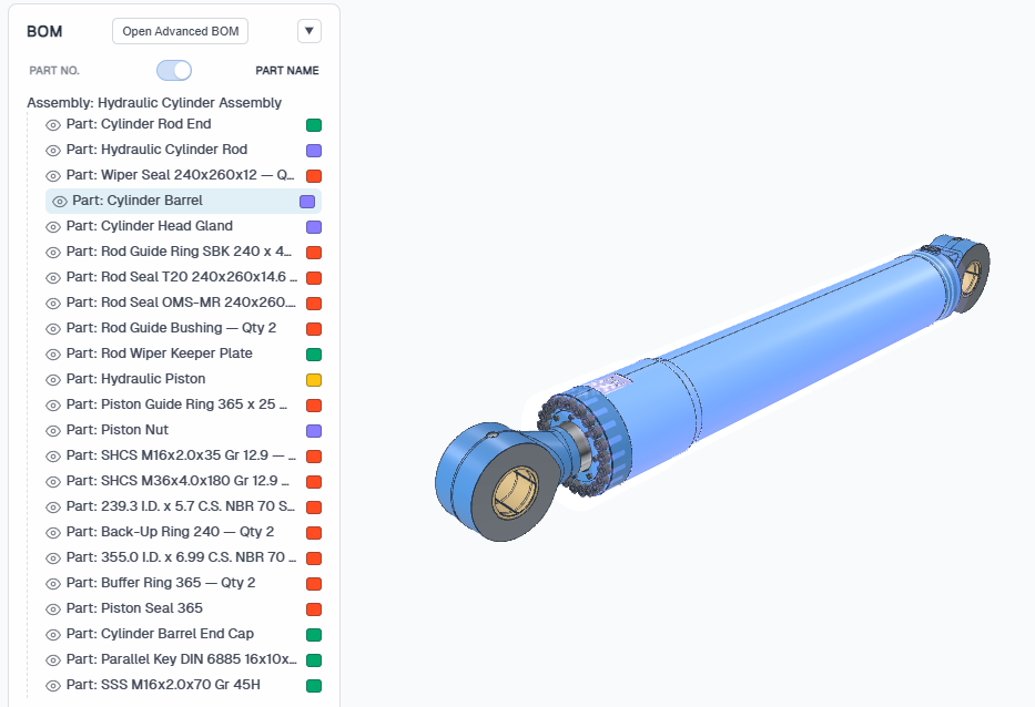
Pulse flashes status colors once so you can see which parts already have an outcome. Show Highlights keeps those status colors on until you click Hide Highlights. On a CAD model the colors appear on the 3D parts. On a schematic they appear on the highlight markers you placed with Highlight Sync.
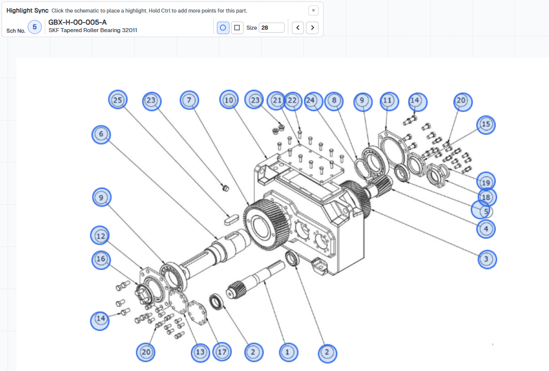
Highlight Sync is optional. Use it only when the report has a schematic and you need to pin each part to a callout on the drawing so Pulse and Show Highlights know where to light up. It is in the BOM panel when a schematic is present, and hidden while Advanced BOM is open.
How to add highlights to the schematic
- Open Highlight Sync — Click Highlight Sync under Part Status in the BOM panel. The Highlight Sync bar appears over the schematic.
- Choose the part — The bar shows the schematic number, part number, and part name. Use the previous and next arrows to move through the BOM.
- Set shape and size — Pick a circle or square marker and adjust Size so the highlight matches the callout on the drawing.
- Click to place — Click the schematic where that part is shown. A new click replaces the previous point for this part. Hold Ctrl (or Cmd on Mac) and click to add extra points when one part appears in more than one place.
- Move to the next part — Step through the list and place a marker for each part you want Pulse and Show Highlights to cover. Close Highlight Sync when you are done — placements save on the part.
Work bar
The floating toolbar at the bottom of the viewport has four tools for inspecting the model: Section, Animate, Appearance, and Origin.
Section
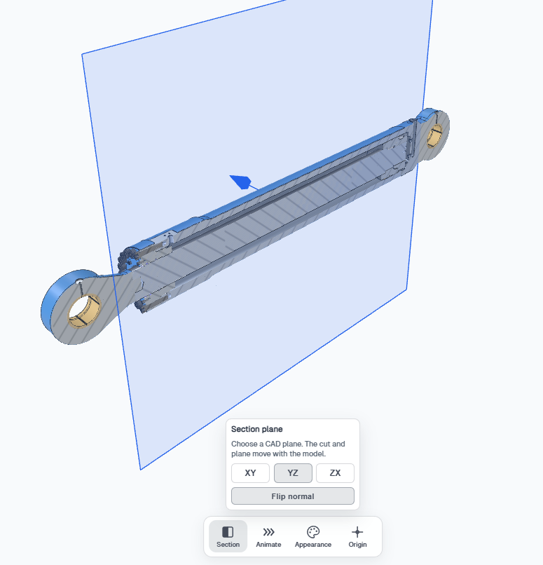
Cuts the model on a CAD plane so you can see inside. Choose XY, YZ, or ZX. The cut moves with the model. Use Flip normal to look at the other side of the plane.
Animate
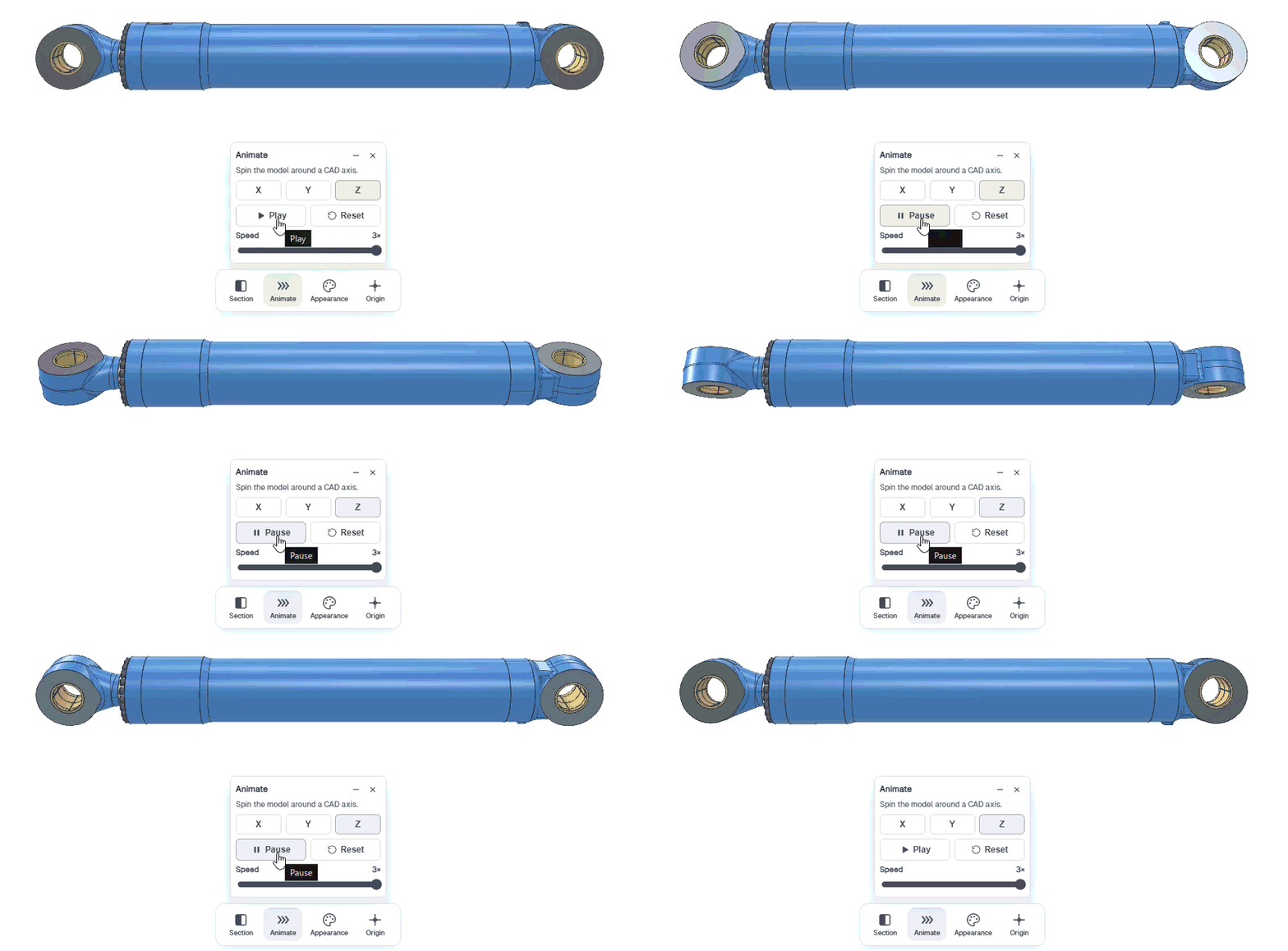
Spins the model around the CAD X, Y, or Z axis. Play, pause, and adjust speed from the Animate panel. Minimize the panel to keep playback going, or close it to stop and return the model to rest.
Appearance
Changes how a selected part looks in the viewer — color, metalness, and roughness. Isolate a part to paint individual faces. You can apply default material colors, project appearances saved on this model, or recipes from Global Settings.
Origin
Toggles the coordinate triad in the viewport. Turn Origin on when you need to see X, Y, and Z while you section, animate, or set orientation.
View cube
The View panel in the lower right snaps the camera to standard orientations: Iso, Top, Back, Left, Front, Right, and Bottom.
- Home — Front view, center the model, and restore fit zoom
- Fit — zoom so the whole model fills the viewer without changing orientation
- Set — rotate 90° / −90° on X, Y, and Z to establish a new baseline orientation
How to reset the orientation
Click Home to return to Front, center the model, and restore the fit zoom. That is the quick reset after orbiting or zooming.
If Front is not how the assembly should sit, click Set, turn Origin on so the triad stays at the viewer center, then use Rotate 90 / Rotate −90 on X, Y, and Z until the model lines up. Click Done to save that as the new baseline. After that, Home uses the orientation you set.
Evaluation Procedures and Report Editor
Two buttons in the top-right of the viewer open the side panels you use while inspecting:
- Evaluation Procedures — opens the checklist of procedures linked to parts in this assembly. See the Evaluation Procedures guide for how the catalog is managed.
- Report Editor — opens the report so you can write blocks, add photos, and fill analysis without leaving the model. See the Report Editor guide.
These panels share a dock. Switch tabs at the top of the panel, or use split view to stack Evaluation Procedures above the Report Editor.
If you get stuck
- The model is not showing yet — conversion may still be running in the background. Wait, or check New Report and Upload.
- You cannot orbit or pan — open ? → Viewer Controls and switch Mouse vs Trackpad. The demos above match that help panel.
- Status colors are not on the model — click Pulse or Show Highlights. On a schematic, place Highlight Sync markers first.